

Transfer Function Damping Ratio
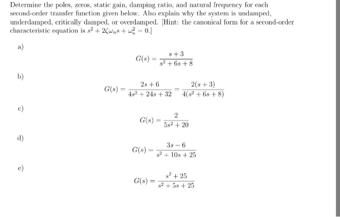
Solved Determine The Poles Zeros Static Gain Damping R Chegg Com
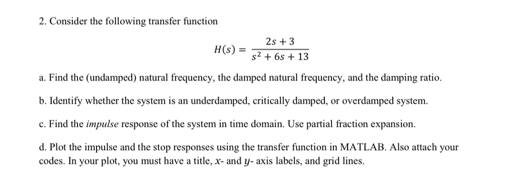
Solved 2 Consider The Following Transfer Function 2s 3 Chegg Com
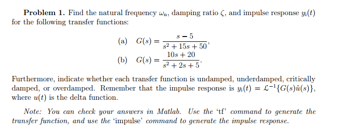
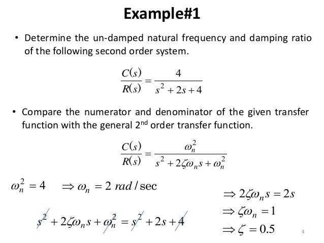
Solved Problem 1 Find The Natural Frequency Wn Damping Chegg Com
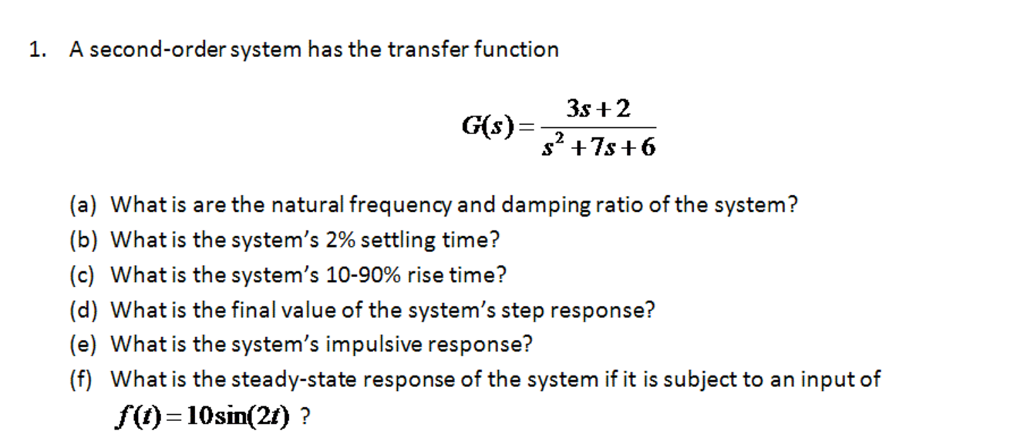
Solved A Second Order System Has The Transfer Function G Chegg Com
Help
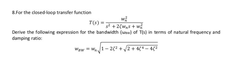
Answered 8 For The Closed Loop Transfer Function Bartleby

Construct a transfer function.
Transfer function damping ratio. For example transfer function is an example of a critically damped system. Concurrently the step response of the system displays oscillations. The quote above is taken from Wikipedia.
3272011 Yes thats the case for a second order lowpass system or a second order lowpass section of a more complex system. Damping ratios of each pole returned as a vector sorted in the same order as wn. Solve for the damping ratio of the given system if the transfer function is X sF s.
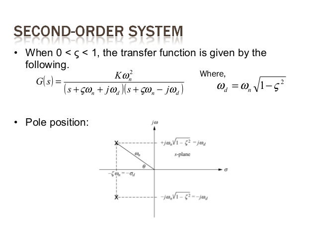
The Overflow Blog Level Up. The damping factor d is defined as dcosalpha. Assuming a damping ratio ζ 025 and natural frequency ω 0 3 rads create the second order transfer function.
The default constructor is TransferFunction num den where num and den are lists of lists of arrays containing polynomial coefficients. Damping is in excess. The system has two real roots both at -4.
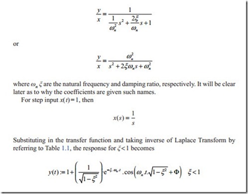
6222020 When the system transfer function has poles with a low damping ratio the Bode magnitude plot displays a resonant peak. The damping ratio is a parameter usually denoted by ζ zeta1 that characterizes the frequency response of a second order ordinary differential equation. The transfer function of a second order lowpass system H s takes the form H L P s A 0 ω 0 2 s 2 2 ζ ω 0 s ω 0 2 Note that at low frequencies frequencies can be seen by replacing s with jω H jω approaches A0.
5262009 Once you have mathematical expressions for the roots as a function of K you can write the transfer function as a product of a first order system with a second order system. It is expressed as the ratio of the numerator and the denominator polynomials ie G s n s d s. From the transfer function PD control allows for both the damping ratio and natural frequency to be controlled separately.
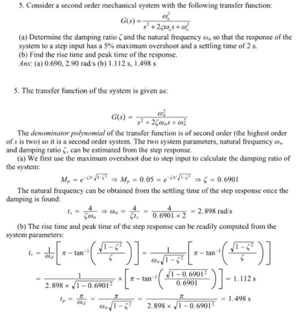
Consider A Second Order Mechanical System With The Following Transfer Function G S A Determine The Damping Ratio And The Natural Frequency Wn So That The Response Of The Syistem To A Step

Solved Bode Plot Open Loop Transfer Function Second Order Break Point 1 Answer Transtutors
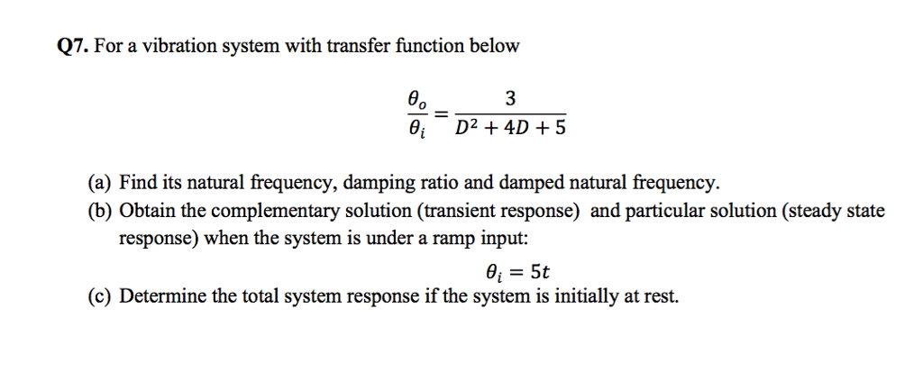
Solved Q7 For A Vibration System With Transfer Function Chegg Com
Lecture 14 15 Time Domain Analysis Of 2nd Order Systems
Feedback Control Theory Second Order Transfer Function Electric Equipment
Chapter 5
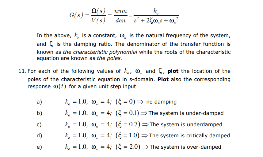
Solved 2 Num G S 0 In The Above K Is A Constant Is Th Chegg Com
Transient Steady State Response Analysis Ppt Video Online Download
Engineer On A Disk

How To Find Damping Ratio Of A 4th Order System Electrical Engineering Stack Exchange

How Do I Find The Second Order Transfer Function From This Step Response Diagram Electrical Engineering Stack Exchange
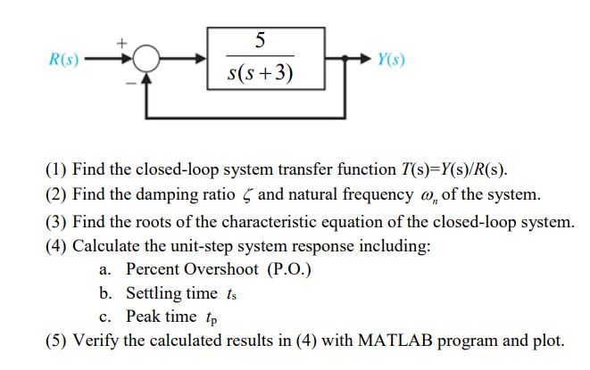
Solved R S Y S 1 Find The Closed Loop System Transfer Chegg Com
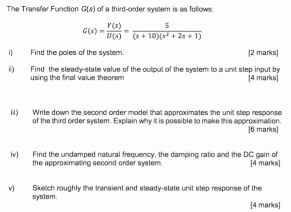
Solved The Transfer Function G S Of A Third Order System Chegg Com
