

Transfer Function Lcr Circuit

Rlc Circuit Magnitude Of The Transfer Function Electrical Engineering Stack Exchange
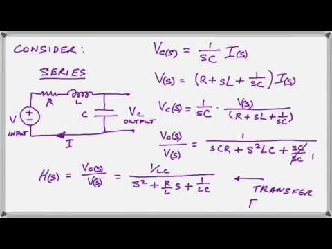
Transfer Functions For Rlc Circuits And Motors Youtube

Rlc Circuit Transfer Functions Electrical Engineering Stack Exchange
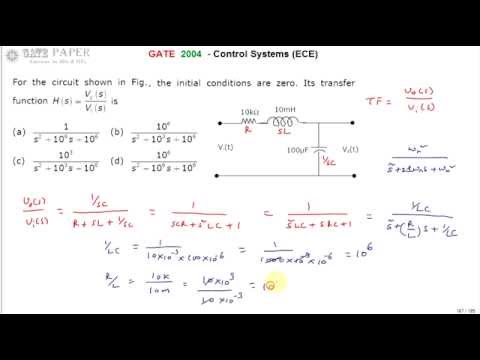
Gate 2004 Ece Transfer Function Of Series Rlc Circuit Given Youtube
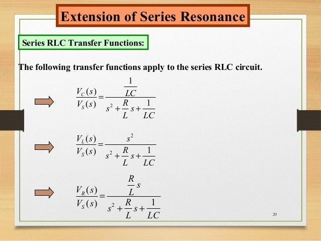
Series Rlc Circuit

Series Rlc Circuit Analog Rf Intgckts
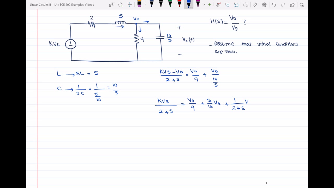
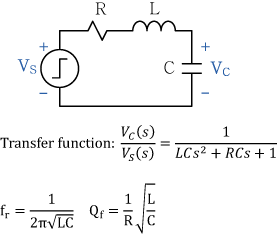
A transfer function is simply a ratio between input and output.
Transfer function lcr circuit. Summary of the properties of RLC resonant circuits. Second Order Transfer Function zThe series resonant circuit is one of the most important elementary circuits. 1Write differential equations of the system.
Procedure for finding the transfer functions of electric networks. Power frequencies 2 1 2 0 1 22 RR LL ω ω 2 2 0 1 22 RR LL ω ω 2 1 2 0 11 22RC ω 1 ω. Transfer Function of Electrical Circuit.
The frequency where the output voltage is 1 2 times the input voltage is given by f 0 R 2 π L So either the circuit drawn does not reflect the circuit measured or something went terribly wrong with your measurement apparatus or operator of said apparatus. 1 Z v j i j ω ω. Procedure for determining the transfer function of a control system are as follows.
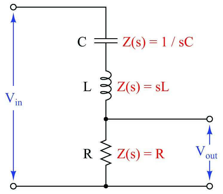
Z C Z C. Calculation of input impedance output impedance and voltage transfer function of an LCR circuitby Arnold Knott Technical University of Denmark DTUhttps. 26 Filtering Signals 2 IMPEDANCE AND TRANSFER FUNCTIONS Response Channel to Scope Ch 1.
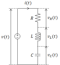
Ohms Law applied to a LCR loop Figure 1 can be written in complex notation see Appendix from the Prerequisite Figure 1 LCR circuit for resonance studies. Transfer Functions of RLC Circuits Solved Example Problems. 7242011 Also regarding that question remember that these relationships for current hold for the inductor and capacitor as well and since this is a series circuit each of these is equal to the current flowing through the entire circuit at all times.
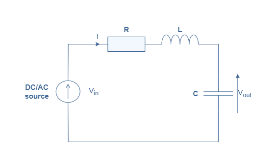
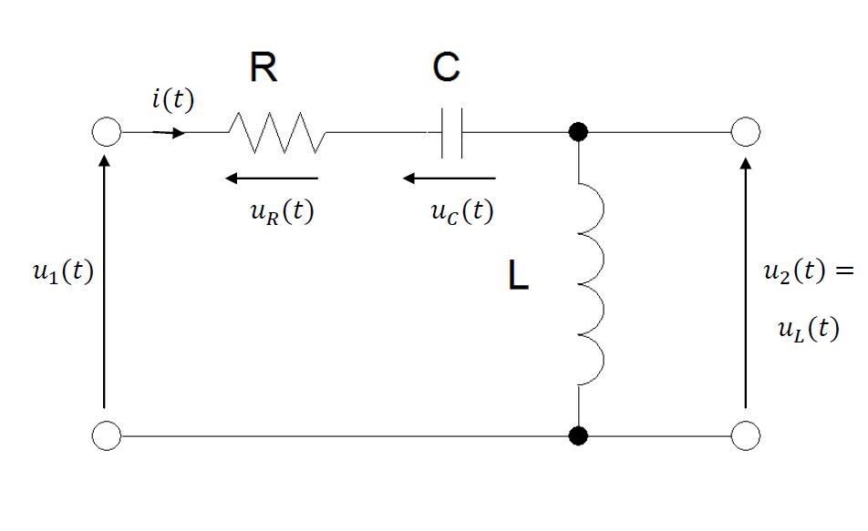
10112020 Transfer Function of LC Circuit The transfer function from the input voltage to the voltage across capacitor is Similarly the transfer function from the input voltage to the voltage across inductor is Natural Response of LC Circuit. The poles must lie in the left half of the s-plane if bounded input leads to bounded output. Series Parallel Circuit R R C VR -Vs I I R LC st IRt Transfer function 2 2 1 VR RC H Vs LC RC ω ω ωω 2 2 2 R S I L H I R LCR L ω ω ωω Resonant frequency 0 1 LC ω 0 1 LC ω.

How To Use Mason Rule To Obtain Transfer Function Of Simple Rlc Electric Circuit
Rlc Circuit Transfer Function Calculation Using Matlab Electrical Academia
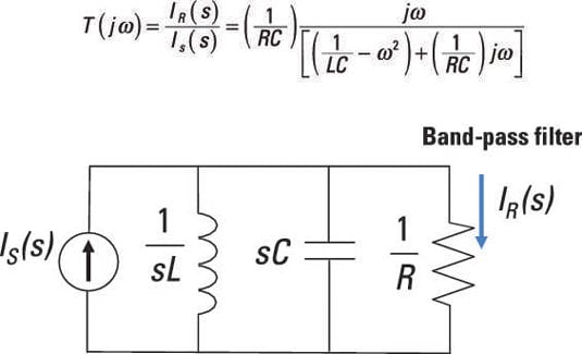
Create Band Pass And Band Reject Filters With Rlc Parallel Circuits Dummies
Series Rlc Circuit Analysis Electronics Lab Com
Finding A Dynamic Model For An Electrical Rlc Circuit

Consider The Rlc Circuit Below A Write The Transfer Function Between Eo S And Ei S In Terms Of R L And C In Standard Canonical Form B We Know The Inductance Of The

Parallel Rlc Transfer Function Electrical Engineering Stack Exchange
Finding The Transfer Function Of A Circuit Youtube

Frequency Response Rlc Circuit Youtube
Resonant Circuits
Step Response Of An Rlc Circuit
Transfer Function Analysis Basic Alternating Current Ac Theory Automation Textbook
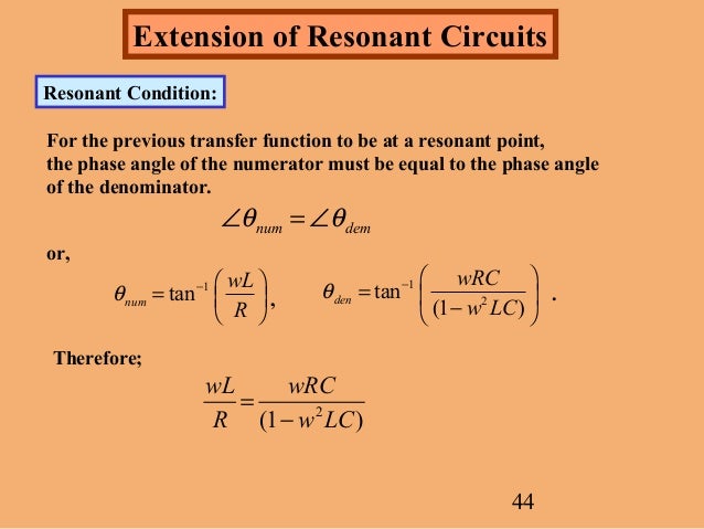
Resonant Circuits
