Transfer Function Parallel Rlc Circuit

Parallel Rlc Transfer Function Electrical Engineering Stack Exchange
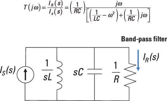
Create Band Pass And Band Reject Filters With Rlc Parallel Circuits Dummies

Rlc Circuit Transfer Functions Electrical Engineering Stack Exchange

Parallel Rlc Circuit And Rlc Parallel Circuit Analysis
Parallel Rlc Circuit Analysis Electronics Lab Com
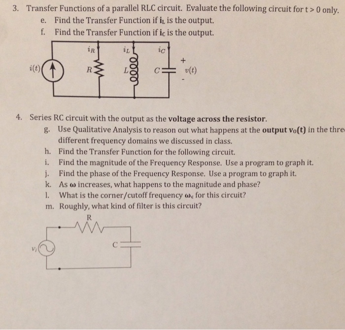
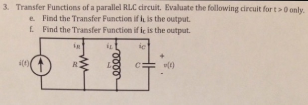
Solved Transfer Functions Of A Parallel Rlc Circuit Eval Chegg Com
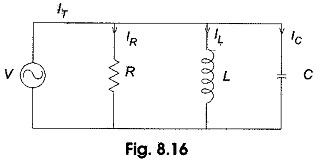
The circuit forms a harmonic oscillator for current and resonates in a similar way as an LC circuit.
Transfer function parallel rlc circuit. The s-domain ratio of the Laplace transform of the output response to the Laplace transform of the input source ℒ ℒ Example. This is a pre-requisite study for Laplace Transforms in circuit analysis.
Here we will compute the phase and the magnitude of the voltage transfer function VoV1 for frequencies ranging from 10 Hz to 100 kHz. 134 The Transfer Function Transfer Function. Current in a parallel R-C circuit is the sum of the current through the resistor and capacitor.
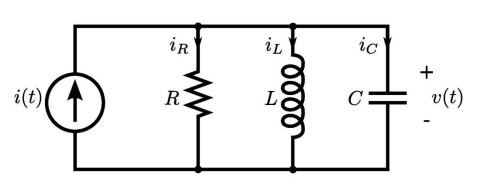
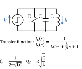
Parallel RLC Second Order Systems Consider a parallel RLC Switch at t0 applies a current source For parallel will use KCL Proceeding just as for series but now in voltage 1 Using KCL to write the equations. 0 0 1 vdt I R L v dt di C t 2 Want full differential equation Differentiating with respect to time 0 1 1 2 2 v dt L dv R. 1Ztot 1Xc 1XL 1R Ztot s R L s2 R L C sL R The voltage input is going to be the voltage output and the transfer function would be just 1.
Find the Transfer Function if i_1 is the output. X s Y s H s A single circuit may have many transfer functions each corresponds to some specific choices of input and output. You call that Kickoffs Law.
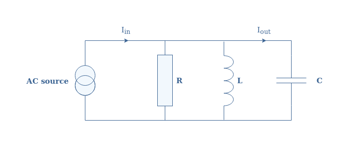
An RLC circuit is an electrical circuit consisting of a resistor an inductor and a capacitor connected in series or in parallel. What is the transfer function of a circuit. You can use current division to find the current transfer function of the parallel RLC circuit.
An RLC circuit has a resistor inductor and capacitor connected in series or in parallel. 11132020 So the transfer function is the same as the output in the case of an impulse input. What is important to understand is that are several transfer functions defined that depend on the choice of input and output variables.
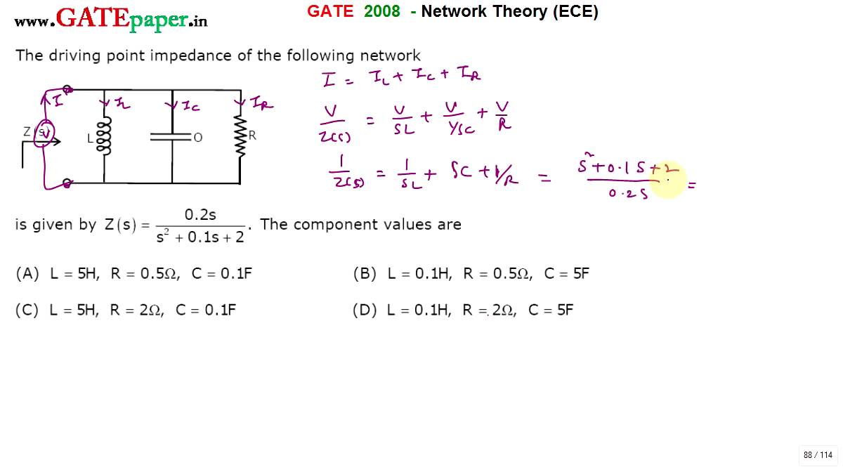
Gate 2008 Ece Find R L And C Component Values Of Parallel Rlc Circuit For Given Z S Youtube
Solved A Derive The Transfer Function H 2 F For This P Chegg Com
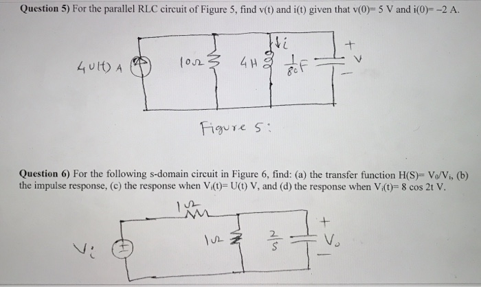
Solved Question 5 For The Parallel Rlc Circuit Of Figure Chegg Com

Solved Ic I T Cv T A Derive The Transfer Function H A Chegg Com
Https Www Sonoma Edu Esee Courses Ee442 Hw Sp17 Hw03 Solutions Pdf

L13 3 2 Step Response Parallel Rlc Youtube
Solved Transfer Functions Of A Parallel Rlc Circuit Eval Chegg Com

Shunt Circuit Feedback Transfer Functions Here Rl C Labels The Series Download Table
Parallel Rlc Circuit What Is It Circuit Analysis Electrical4u
Step Response Of An Rlc Circuit
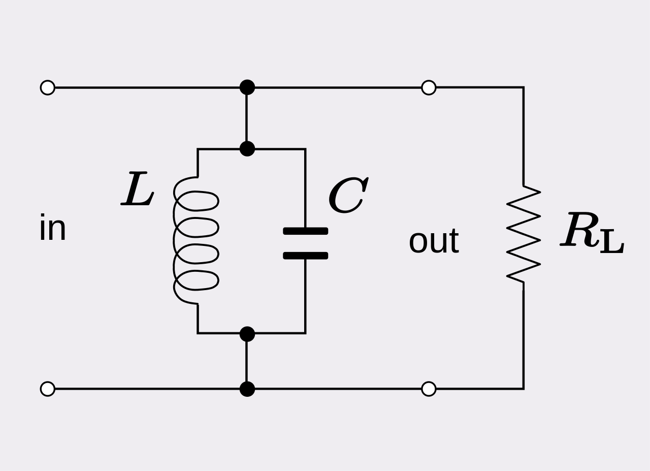
File Rlc Parallel Band Pass Svg Wikipedia

Parallel Rlc Circuit And Rlc Parallel Circuit Analysis
Quality Factor Of Parallel Rlc Circuit