

Transfer Function Q Factor

Q Factor What Is It And How Do You Measure It Electrical4u

Sallen And Key Filter Design For Second Order Rc Filters
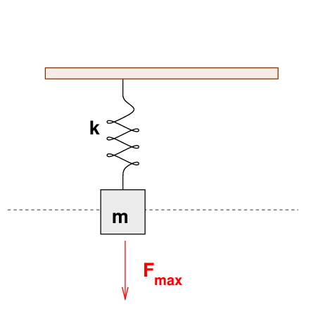
Step Response Of An Rlc Circuit

Second Order Filters Second Order Low Pass Filter

Q Factor An Overview Sciencedirect Topics

Q Factors An Overview Sciencedirect Topics

The energy stored in the circuit is 2 11 S 22 E LI CVc2 114.
Transfer function q factor. Where μ 0 and μ 1 are the mean values and σ 0 and σ 1 are the variances of the probability density functions px x 0 and px x 1. We can express now the complex transfer function with the Q factor combining equations 6 and 11. Q factor as a function of the bandwidth in octaves N octave bandwidth Bandwidth in.
Hence it is a very important parameter form of the transfer function in the region between passband and stopband. This results in flat filter flanks with a large bandwidth. A low filter quality means broad-band filtering with a small Q factor.
And I also have my component values. Hjω as function of ωω. 10222020 A transfer function represents the relationship between the output signal of a control system and the input signal for all possible input values.
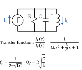
So its a buck converters so we have a second-order transfer function with a pair of poles center frequency of the pole is basically given by the corner frequency of this LC filter. F c Hz. The Q-factor of the filter is adjusted by VR1 while the centre-frequency is adjusted by VR2.
The transfer function of the filter is as follows. Note that for Q values below 1 the amplitude of the hp and lp outputs is 1Q times higher than the bp output. An introduction to Laplace-transform analysis appears in Appendix D.
Define a parameter called the Quality Factor Q which is related to the sharpness of the peak and it is given by maximum energy stored 22 total energy lost per cycle at resonance S D E Q E ππ 113 which represents the ratio of the energy stored to the energy dissipated in a circuit. We define Q in the context of continuous-time resonators so that the transfer function is the Laplace transform of the continuous impulse-response instead of the z transform of the discrete-time impulse-response. More fundamentally the Q factor of a resonance is 2π times the stored energy divided by the energy lost per oscillation cycle.

Second Order Filters Second Order Low Pass Filter
Q Factor Of An Oscillating System

Q Factors An Overview Sciencedirect Topics

Q Factor An Overview Sciencedirect Topics
Http Www Iosrjournals Org Iosr Jce Papers Vol17 Issue1 Version 2 E017122733 Pdf

Q Factors An Overview Sciencedirect Topics

Second Order Filters Second Order Low Pass Filter

Band Pass Filter What Is It Circuit Design Transfer Function Electrical4u

Second Order System An Overview Sciencedirect Topics

Transfer Functions An Overview Sciencedirect Topics

Q Factor Of An Oscillating System
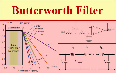
Butterworth Filter Design Equations And Calculations

High Quality Factor An Overview Sciencedirect Topics