Transfer Function Zeta
Consider The 2 Nd Order Transfer Function G S O Chegg Com
Solved For The Standard Second Order Transfer Function Of Chegg Com

Solved The Standard Form For The Second Order System Tran Chegg Com
Solved For Each Of The Following Transfer Function Do Th Chegg Com
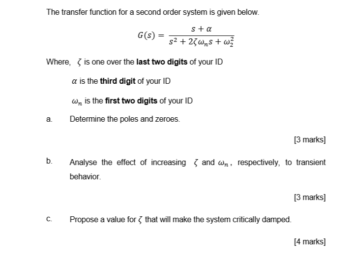
Solved The Transfer Function For A Second Order System Is Chegg Com

Second Order Transfer Function Signals And Systems Lecture 32 Slides Electrical And Computer Engineering Docsity

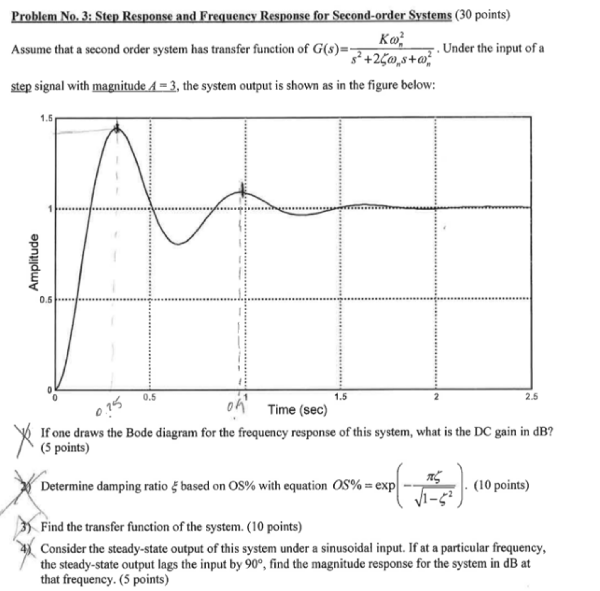
Concurrently the step response of the system displays oscillations.
Transfer function zeta. H s 50 60 s s 160182 185211 s s 2 0499706 s 425833 Your transfer function does not look like second order transfer functions. In mathematics and signal processing the Z-transform converts a discrete-time signal which is a sequence of real or complex numbers into a complex frequency-domain representation. The system has two real roots both at -4.
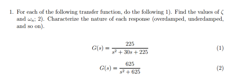
So keeeping wn and K constantif you find the poles of. It is expressed as the ratio of the numerator and the denominator polynomials ie G s n s d s. For example transfer function is an example of a critically damped system.
Hence mathematically we can observe that it should be zero when radius is at ˇ and it is a low pass lter. The simplest invariant measures for a dynamical system are those carried by periodic orbits. The damping ratio is a parameter usually denoted by ζ zeta that characterizes the frequency response of a second-order ordinary differential equation.
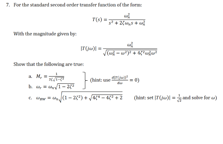
The effect of varying damping ratio on a second-order system. This has to be 10. 10222020 A transfer function represents the relationship between the output signal of a control system and the input signal for all possible input values.
If we use polar coordinate system zrej the zero is at r1 with ˇradius. 6222020 When the system transfer function has poles with a low damping ratio the Bode magnitude plot displays a resonant peak. A block diagram is a visualization of the control system which uses blocks to represent the transfer function and arrows which represent the various input and output signals.
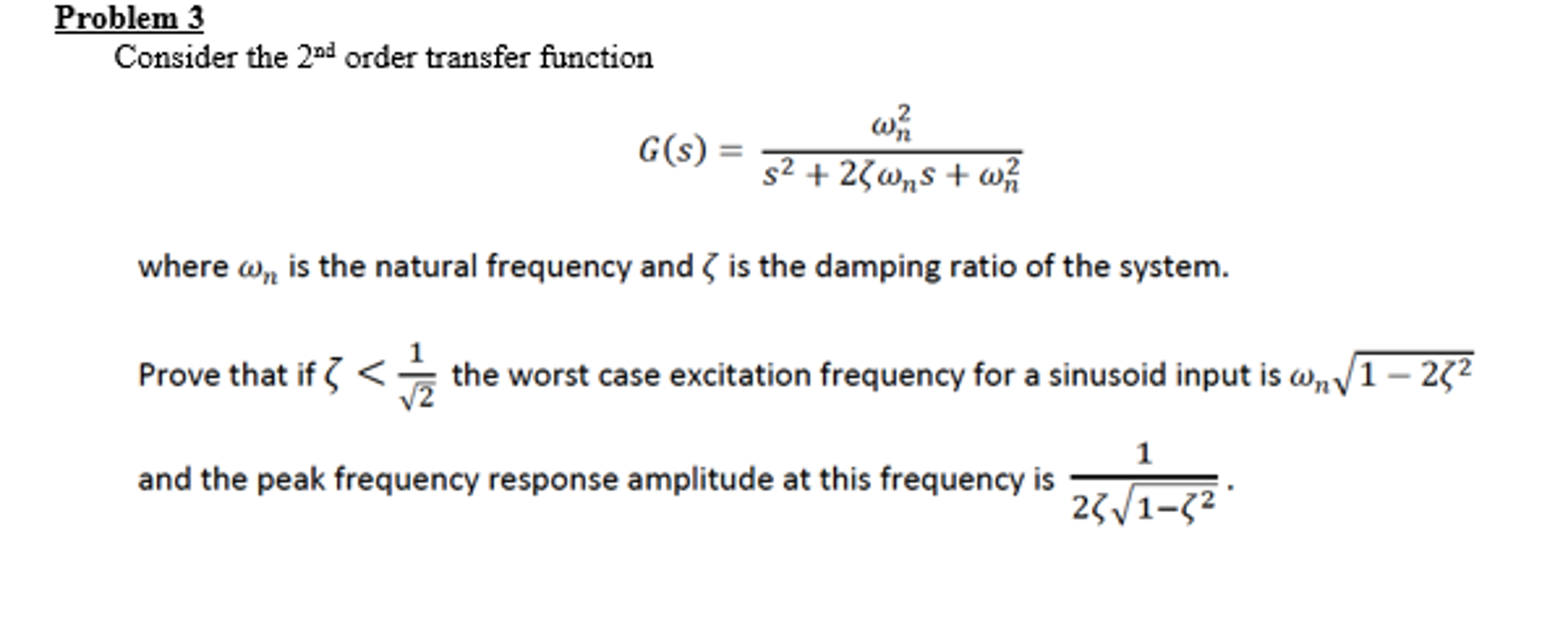
Zeta represents damping ratioAnd other parameters are natural frequency wn and steady state gain K. The transfer function of a discrete-time linear system ABCD is the ratio G z C zI A 1 B D between the Z-transform Y z of the output and the Z-transform U z of the input. To illustrate this relationship we consider a prototype second-order systems.

Gate 2008 Ece Match Step Response Of Second Order System With Transfer Functions Youtube
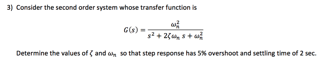
Solved Consider The Second Order System Whose Transfer Fu Chegg Com

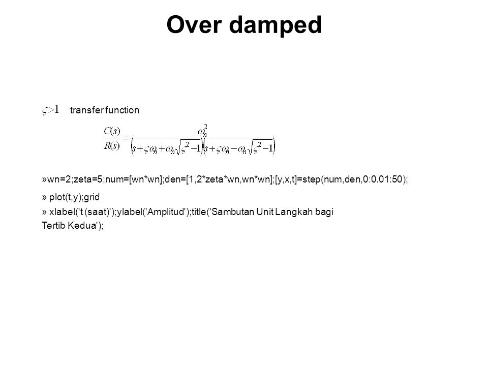
2nd Order System Dynamics
Http Www Ee Ic Ac Uk Pcheung Teaching De2 Ee Lecture 207 20 20step 20response 20 20system 20behaviour 20 X1 Pdf

Control Tutorials For Matlab And Simulink Introduction System Analysis

Solved The Standard Second Order Transfer Function Has Th Chegg Com
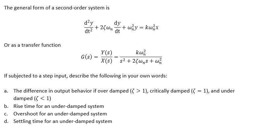
Solved The General Form Of A Second Order System Is D 2y Chegg Com
3 0 Time Response Objective Ppt Video Online Download

How Do I Find The Second Order Transfer Function From This Step Response Diagram Electrical Engineering Stack Exchange
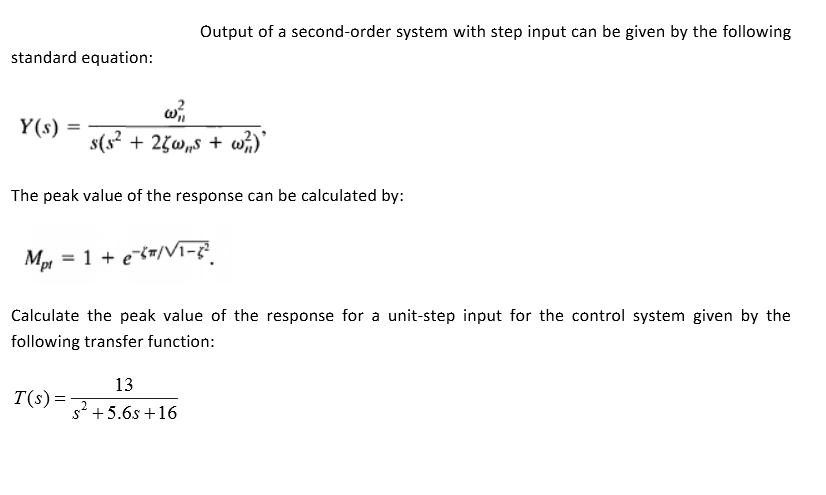
Solved Output Of A Second Order System With Step Input Ca Chegg Com
List Of Corrections

Control Tutorials For Matlab And Simulink Introduction System Analysis

Determination Of Pid Controller Parameters From Step Response Specifications