Power Flow Transfer Equation For A Synchronous Generator
Power Flow Transfer Equations Eeeguide Com
Power Flow Transfer Equations Eeeguide Com

Power Flow Transfer Equations Eeeguide Com
Power Flow Transfer Equations Eeeguide Com
Power Flow Transfer Equations Eeeguide Com

Power Flow Transfer Equations Eeeguide Com
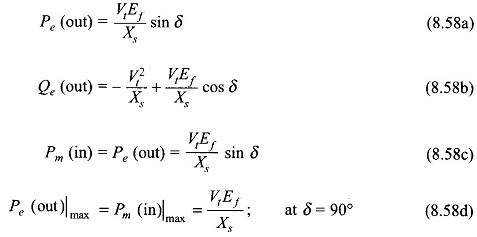
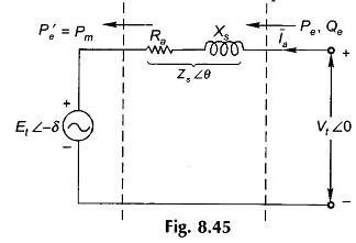
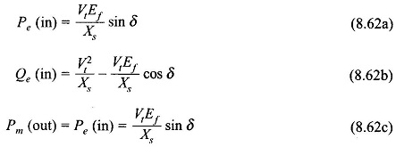
The complex power delivered by the generator to the system is.
Power flow transfer equation for a synchronous generator. The equation is general and can be well applied for Synchronous generator Synchronous Motor. Get E A from air-gap line on OCC 2. The total power developed would be three.
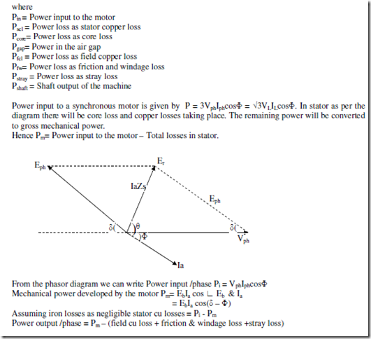
X d synchronous transient resistance of the machine. It can also write in phase form. E b Back emf phase.
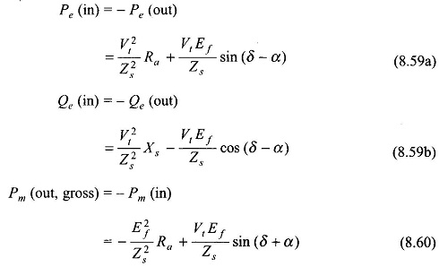
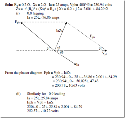
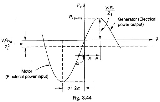
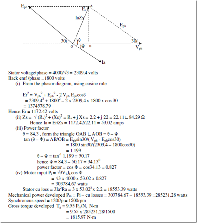
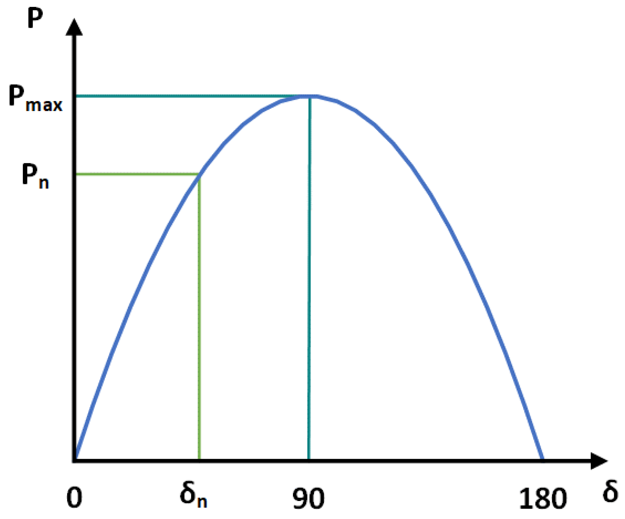
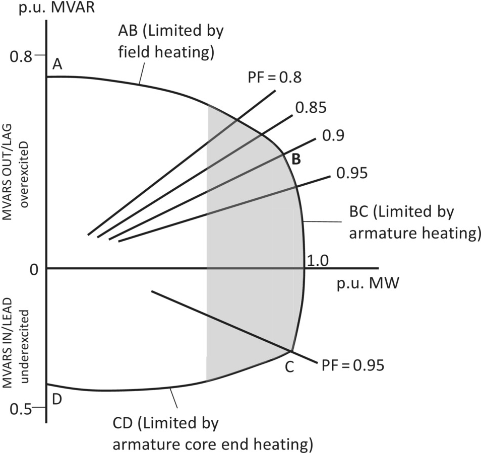
The power flow diagrams are discussed in more detail below but first we will consider the losses in the synchronous machine. - δ0 153612 2681rad Critical clearing angle δc Critical clearing time tc 026 second A synchronous generator is connected to a large power system and supplying 045 pu MW of its maximum power. Let V terminal voltage per phase E f excitation voltage per phase I a armature current phase angle between E f and V The phasor diagram at lagging power factor is shown in fig B.
V -ri - λ Vn 3 4 Where Ld Equivalent direct-axis Reactance LF Filed winding Self inductance LD Self-inductance damper winding. Let Active power transferred to the system. The difference of the power input to the synchronous motor and the power output to the synchronous motor gives ohmic losses in the generator.
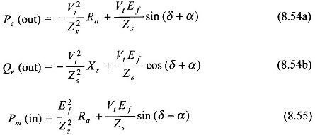
1 Shows the phasor diagram of the salient-pole synchronous generator. Equation 1 shown above is the EMF equation of the Synchronous Generator. 1062019 Power of the Synchronous Generator.
Inductance and resistance of line and the impedance angle. Synchronous Machines Active power will flow when there is a phase difference between Vsend and Vreceive. 3282015 Calculate the emf induced in the motor if it is operating at a power factor i 08 lagging ii 09 leading.
Power Flow Transfer Equations Eeeguide Com
Power Flow Transfer Equations Eeeguide Com
Power Flow In Synchronous Motor Electric Equipment
Power Flow In Synchronous Motor Electric Equipment
Power Flow In Synchronous Motor Electric Equipment

Power And Torque In Synchronous Generator The Engineering Knowledge
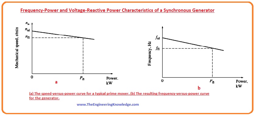
Frequency Power And Voltage Reactive Power Characteristics Of A Synchronous Generator The Engineering Knowledge

Frequency Power And Voltage Reactive Power Characteristics Of A Synchronous Generator The Engineering Knowledge
Http Schevalier Com Wp Content Uploads 2017 02 Synchronous Generator Model Pdf

Is There Any Way That We Can Make The Active Power Of The Synchronous Generator To Zero
Energies Free Full Text Synchronous Generator Out Of Step Detection Using Real Time Load Angle Data Html
The Alternating Current Generator Chapter 15 Gas Turbines For Electric Power Generation

What Is The Equivalent Circuit Of Synchronous Generator The Engineering Knowledge