

Transfer Function Harmonic Oscillator

Quantum Harmonic Oscillator Quantum Mechanics Quantum Physical Science

Transfer Function Of A Driven Damped Harmonic Oscillator With A Download Scientific Diagram

In Simple Harmonic Motion The Position Is A Periodic Sinusoidal Function Of Time Value Of Sine Function Is Always Betwee Esquemas Electricos Fisica Esquemas

Transfer Function Of A Driven Damped Harmonic Oscillator With A Download Scientific Diagram

Simple Harmonic Oscillator Wave Function Energy Values Comparison With Wave Function Classical Mechanics Quantum Mechanics

Transfer Function Of A Driven Damped Harmonic Oscillator With A Download Scientific Diagram
The oscillator equation is rewritten inserting the previous complex harmonic functions for f and q.
Transfer function harmonic oscillator. A method for. A damped harmonic oscillator is displaced by a distance x 0and released at time t 0. One pole of its open loop transfer function is at RHS in such cases calculation of GM PM is not a suitable method to find the stability.
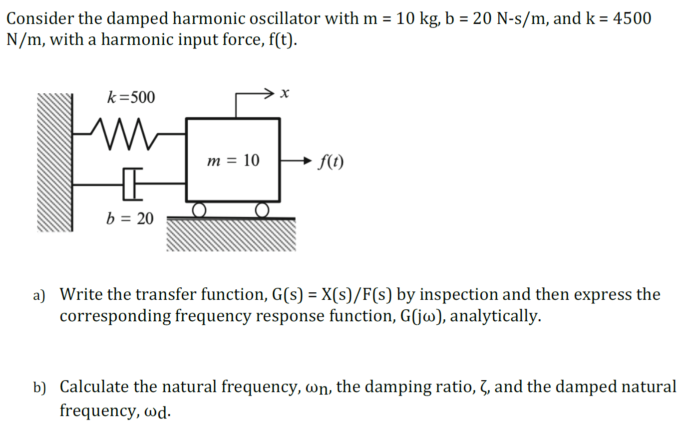
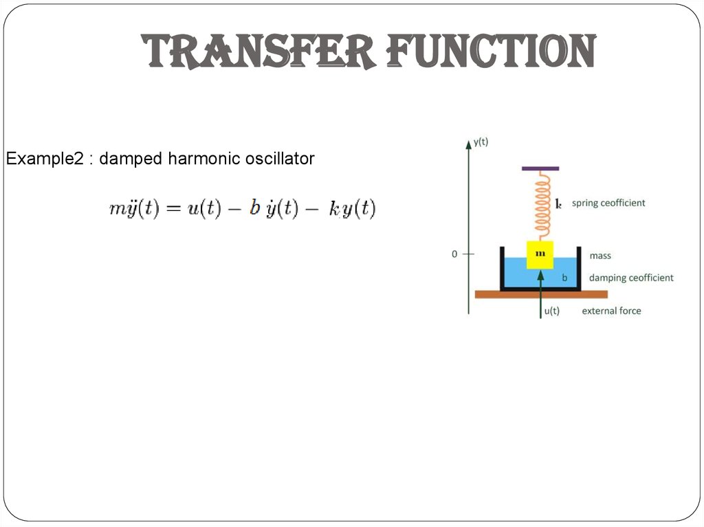
This ratio is called the transfer function between the forcing and the displacement response. By changing the slider values for θ and ω the step response for the corresponding system is displayed. Take for example the differential equation for a forced damped harmonic oscillator mx00bx0kx ut41 Note that we changed the driving force to ut.
Transfer Functions and State Space Blocks 41 State Space Formulation There are other more elegant approaches to solving a differential equation in Simullink. The natural response of the simple harmonic oscillator contains the response mode. 352021 The oscillator transfer function G s 1 s 2 ω n 2 has simple poles p 1 2.
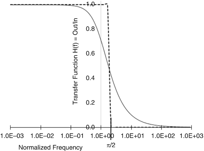
J ω n on the j ω -axis. It is a complex function. For small amplitudes the higher order terms have little effect.
The nonlinear transfer function can be expressed as a Taylor series. For larger amplitudes the nonlinearity is pronounced. Specifically we find the frequency-domain response of the harmonic oscillator to an arbitrary driving force Dt by calculating the Fourier transform D ω of the driving force then multiplying it by the transfer function xhD ω ωω 11.
Consequently for low distortion the oscillators output amplitude should be a small fraction of the amplifiers dynamic range. Gain margin GM. 11282015 The system itself is governed by the transfer function which relates output to input.

Hamilton Systems System First Order Pie Chart

Transfer Function Of A Driven Damped Harmonic Oscillator With A Download Scientific Diagram
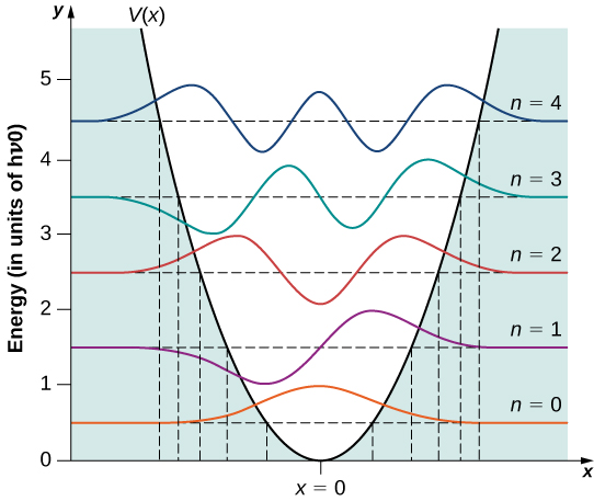
The Quantum Harmonic Oscillator University Physics Volume 3
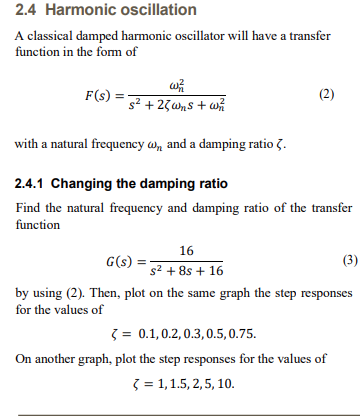
Solved 2 4 Harmonic Oscillation A Classical Damped Harmon Chegg Com
Solved Consider The Damped Harmonic Oscillator With M 1 Chegg Com

Physical Chemistry Physical Chemistry Introduction To Quantum Mechanics Quantum Mechanics

Tetryonics 21 10 Electromagnetic Exchange Particles

Wigner Distribution Function For The Equilibrium State Of A Harmonic Download Scientific Diagram

Translational Partition Function Of A Particle Confined In A Box Thermodynamics Mechanical Energy Physical Chemistry

Elimination Reactions Chapter 17 Organic Chemistry Study Organic Chemistry Teaching Biology
The Simple Harmonic Oscillator Springerlink

Scene Behind Camera How I Shoot Record Edit And Upload Videos Online Ph In 2020 Video Online Videos Places To Visit
System Models Prezentaciya Onlajn
