

Transfer Function Phase Angle

Bode Plot Transfer Function No Response Separation

Ac Phase Angle Control For Light Dimmers And Motor Speed Control Using 555 Timer And Pwm Signal In 2020 Light Dimmers Electronics Circuit Microcontrollers

Reverse Engineering The Bode Plot Bode Plots Engineering

What Bode Plots Represent The Frequency Domain

Pin On Electrical Equipment Supplies

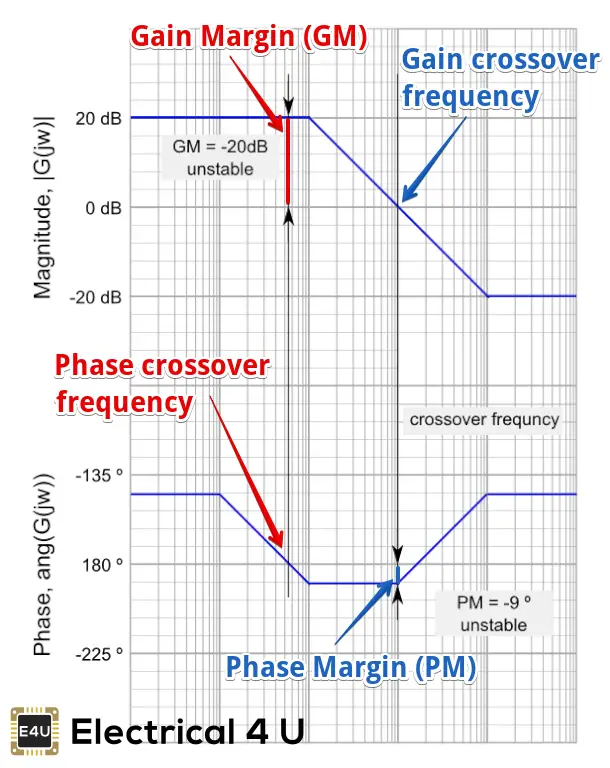
Bode Plot Gain Margin And Phase Margin Plus Diagrams Electrical4u

How to calculate Gain and phase angle of an transfer function.
Transfer function phase angle. In control engineering and control theory the transfer function of a system is a very common concept. H ω 1 1 j ω 1 j ω 10 How is the phase angle obtained when it has multiple poles to get. This transfer function which represents displacement over force is sometimes called the receptance function as shown in Table 1.
How to calculate the phase in degrees. Gain and Phase The gain and phase are found by calculating the gain and angle of the transfer function evaluates at jω. Hz frac zz-05 Then substitue the zHejwfracejwejw-05 Expand to cos and sin.
And u must add 180. 2272012 As gneill pointed out your transfer function phase angle will be the negative of the numerator phase angle ie. To get the correct phase from 0 to -90.
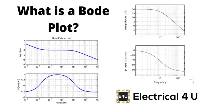
And the phase angle right here on the output is equal to the angle of H plus at that same frequency plus the angle of the input. Bode plots typically consist of two graphs. Eg if ψ 30 deg -ψ is the same as 360 - 30 330 deg not 30 - 180 or 30 180.
The substitution and gr. It is known as the time-shifting property of Laplace transform and is one of the few facts that is worth remembering. A transfer function is determined using Laplace transform and plays a vital role in the development of the automatic control systems theory.
One well call the magnitude plot and one called the phase angle plot. However using a single semi-log paper both logarithmic of magnitude and logarithmic of phase angle values can be sketched against logarithmic frequency. Usually denoted as Hs or Hjomega.
Bode Plot Gain Margin And Phase Margin Plus Diagrams Electrical4u

Scientists Unveil The First Ever Image Of Quantum Entanglement Https Phys Org News 2019 07 Scientist Quantum Entanglement Quantum Mechanics Planetary Science

Scaffolding Trig Graphs Desmos Kong Graphing Precalculus Math Lessons

Graphs From The Unit Circle High School Lesson Plans Teaching Math High School Activities

Pin On Electrical Wiring

Balancing Of Single Phase Loads To Achieve Energy Efficiency Eep Energy Efficiency Efficiency Achievement
Http Www Ee Ic Ac Uk Pcheung Teaching De2 Ee Lecture 208 20 20frequency 20responses 20 Notes Pdf

Menstrual Cycle Sac
Bode Plot Gain Margin And Phase Margin Plus Diagrams Electrical4u

Phases And Wires In Distribution Of Ac Power Eep Power Electrical Engineering Ac Power
Http Www Ee Ic Ac Uk Pcheung Teaching De2 Ee Lecture 208 20 20frequency 20responses 20 Notes Pdf

Microwave Engineering Youtube Engineering Subjects Science Education Class Notes

A Radial Node Is A Sphere Rather Than An Angular Node Which Is A Flat Plane That Occurs When The Radial Wavefunction For Quantum Mechanics Chemistry Physics